It’s hard to overstate the importance of running the right propeller on your boat – whether you’re a top-notch professional angler or weekend recreation warrior. Your propeller is where it all comes together. Where technology meets the water. Where power becomes performance.
Understanding the basic science behind propeller design will help you understand their importance – and help you choose the Mercury prop that best suits your needs and meets your expectations on the water. For a richer, more satisfying boating experience.
How Propellers Work
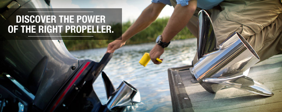
The “Push/Pull” Concept
To understand this concept, let us freeze a propeller just at the point where one of the blades is projecting directly out of the page (Figure 3-1). This is a right-hand rotation propeller, whose projecting blade is rotating from top to bottom and is moving from left to right. As the blade in this discussion rotates or moves downward, it pushes water down and back as is done by your hand when swimming. At the same time, water must rush in behind the blade to fill the space left by the downward moving blade. This results in a pressure differential between the two sides of the blade: a positive pressure, or pushing effect, on the underside and a negative pressure, or pulling effect, on the top side. This action, of course, occurs on all the blades around the full circle of rotation as the engine rotates the propeller. So the propeller is both pushing and being pulled through the water.
Thrust/Momentum
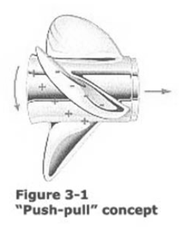
These pressures cause water to be drawn into the propeller from in front and accelerated out the back, just as a household fan pulls air in from behind it and blows it out toward you (Figure 3-2 below).
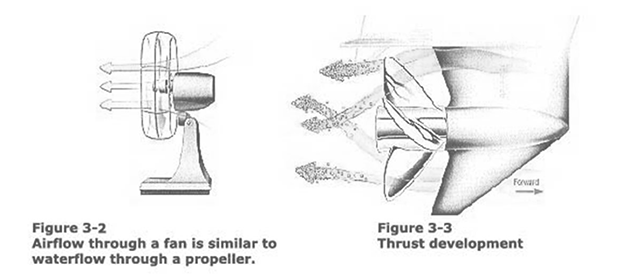
The marine propeller draws or pulls water in from its front end through an imaginary cylinder a little larger than the propeller diameter (Figure 3-3). The front end of the propeller is the end that faces the boat. As the propeller spins, water accelerates through it, creating a jet stream of higher-velocity water behind the propeller. This exiting water jet is smaller in diameter than the actual diameter of the propeller.
This water jet action of pulling water in and pushing it out at a higher velocity adds momentum to the water. This change in momentum or acceleration of the water results in a force which we can call thrust.
Basic Propeller Parts
The first step to understanding propellers and how they work is familiarizing yourself with the basic parts of a propeller. (Figure 2-1)
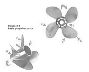 A. Blade Tip – The maximum reach of the blade from the center of the propeller hub. It separates the leading edge from the trailing
edge.
B. Leading Edge – That part of the blade nearest the boat, which first cuts through the water. It extends from the hub to the tip.
C. Trailing Edge – That part of the blade farthest from the boat. The edge from which the water leaves the blade. It extends from the tip to the hub (near the diffuser ring on through-hub exhaust propellers).
D. Cup – A small curve or lip on the trailing edge of the blade, permitting the propeller to hold water better and normally adding about 1/2″ (12.7 mm) to 1″ (25.4 mm) of pitch.
E. Blade Face – That side of the blade facing away from the boat, known as the positive pressure side of the
blade.
F. Blade Back – The side of the blade facing the boat, known as the negative pressure (or suction) side of the
blade.
G. Blade Root – The point at which the blade attaches to the hub.
H. Inner Hub – This contains the Flo-Torq rubber hub or Flo-Torq II Delrin® Hub System (Figures 2-2 and 2-3).
The forward end of the inner hub is the metal surface which generally transmits the propeller thrust through the
forward thrust hub to the propeller shaft and in turn, eventually to the boat.
I. Outer Hub – For through-hub exhaust propellers. The exterior surface is in direct contact with the water. The
blades are attached to the exterior surface. Its inner surface is in contact with the exhaust passage and with the
ribs which attach the outer hub to the inner hub.
J. Ribs – For through-hub exhaust propellers. The connections between the inner and outer hub. There are
usually three ribs, occasionally two, four, or five. The ribs are usually either parallel to the propeller shaft
(“straight”), or parallel to the blades (“helical”).
K. Flo-Torq™ Shock-Absorbing Rubber Hub – Rubber molded to an inner splined hub to protect the propeller drive system from impact damage and to flex when shifting the engine, to relieve the normal shift shock that occurs between the gear and clutch mechanism – generally used with low horsepower applications. Flo-Torq II Shock-Absorbing Delrin® Hub Patented hub system designed to resist slippage, yet flex during engine shifting and cushions the drivetrain upon underwater impact. The Flo-Torq II system makes Mercury Propellers compatible with almost all marine engines.
L. Diffuser Ring – Aids in reducing exhaust back pressure and in preventing exhaust gas from feeding back into
propeller blades
M. Exhaust Passage – For through-hub exhaust propellers. The hollow area between the inner hub and the outer hub through which engine exhaust gases are discharged into the water. In some stern drive installations using a through-transom exhaust system, this passage carries air.
N. Performance Vent System (PVS) – PVS, a patented Mercury ventilation system, allows the boater to custom tune the venting of the propeller blades for maximum planing performance. On acceleration, exhaust is drawn out of the vent hole located behind each blade. When the next propeller blade strikes this aerated water, less force is required to push through this water allowing the engine RPM to rise more rapidly. Water flows over the vent holes once the boat is on plane sending exhaust through the exhaust passage. Varying the size of the exhaust holes
engine RPM can be controlled, outboards perform better with venting and stern drives typically require less venting if any at all.
How to Choose the Right Prop
Pitch
- Identify the make, model, year and horsepower of your engine
- Consult the owner’s manual to find the recommended wide-open-throttle (WOT) RPM range for your
engine. - Using the existing propeller, make a test run to determine the current WOT RPM and speed. Vary the
boat’s trim angle for maximum speed. The boat should be loaded as it would under “normal” operating
conditions. A full tank of fuel is recommended. - If the current propeller isn’t within the manufacturers recommended WOT range, select a propeller with a
larger or smaller pitch using the following rules:- Adding 1 inch of propeller pitch will reduce WOT RPM by 150 to 200 RPM.
- Subtracting 1 inch of propeller pitch will increase WOT RPM by 150 to 200 RPM
- If you’re upgrading from a three-blade propeller to a four-blade propeller, remember that many four-blade propellers generally turn 50 to 100 RPM less than a three-blade propeller with the same pitch.
Deciding Between Stainless vs. Aluminum
Many boats are factory-equipped with aluminum propellers. Aluminum propellers are relatively inexpensive and suitable for general purpose use. Stainless steel propellers are more expensive, but are far stronger and more durable than aluminum.
If you are looking to improve the performance of your boat, upgrading to a stainless steel propeller is the most cost-effective way to get better handling, acceleration or top speed out of your boat. Will a stainless steel propeller damage my lower unit in the event of an underwater impact? Mercury engineers, conducting underwater impact testing, found no substantial difference in the amount of torque transferred to the propeller shaft between an aluminum and stainless steel propeller. Mercury’s Flo-Torq II hub system is designed to give way during an underwater impact – protecting the outboard and still providing you the ability to idle home safely.
Blades
The choice between a three-blade and a four-blade propeller depends mostly on the desired performance characteristics of the boat. A three-blade propeller usually offers better top-speed performance in a non-surfacing piercing application, while a four-blade propeller provides better acceleration and smoother cruising operation. Most propellers are made with three blades as a compromise for vibration, convenient size, efficiency, and cost. The efficiency difference between a two- and a three-bladed propeller is considered less significant than the vibration difference. Most of today’s production propellers are presently either three- or four-bladed. In recent years, with the growing frequency of propellers being run at an increased height (surface piercing), fourand five-bladed propellers have become more popular. They suppress the higher level of vibration and improve acceleration by putting more blade area into the water. They can also help to make the rake more effective in lifting the bow of the boat for added speed.