Call it what you will, blue-water fever, inshore, flats, we all have our preferences when it comes to our favorite species of fish and the waters we enjoy. As for how we get there, the styles of boats are endless from small skiffs or bay boats to large sport-fishing battle wagons. What might not be clear to a would-be angler, what are the real, down and dirty differences between offshore and inshore fishing?
Author: admin
Operator’s Guide: Stepped Hull Boats
Purpose
The intent of this document is to provide a clearer understanding of the operational differences between a stepped-hull vessel and a traditional mono-hull style boat. Specific attention is provided herein to the uses and adjustment of engine trim. As such, this guide assumes that the reader and/or boat operator has experience using throttle-based engine trim controls and is performing the recommendations herein under favorable weather and water conditions. Towards this end, any reference to “trim” or “trimming” within this documents speaks directly to the outboard engine’s angle in the water, not the use of exterior-mounted trim tabs.
Benefits of a Stepped Hulls
A stepped hull design generally grants a boat with a larger degree of deadrise the ability to ride flatter in the water with a cruising height of approximately 3° bow up attitude. The inclusion of steps assist the vessel in achieving more speed, with less horsepower, and improved fuel efficiency versus traditional hulls with the same horsepower. Speaking purely on physics, when on plane, a stepped hull decreases the total wetted surface due to less contact points with the water and thereby lowers overall drag. Given this, while in a turn, the reduction in drag will produce a smaller wake. The end result, a stepped hull will generally be more efficient, use less fuel, and obtain a higher top-end speed.
Default Trim Position at Cruise
When operating a stepped hull, engine trim should be set to 50-60% out for maximum efficiency as this puts the cavitation plate parallel with the water. In contrast, a traditional hull would run with an approximate 25% trim.
Deceleration
When backing off the throttle and as the boat begins to settle, start trimming your engine into the zero-trim position. The zero-trim position should be consider the default and used for the starting point for acceleration.
Accelerating to Plane
To rise up to plane, increase the throttle briskly and begin trimming the engine outward within just a few seconds of acceleration. As speed increases, the operator should continue to add trim until reaching the 50-60% position and an approximate cruising speed of *30 to 40 MHP. *This will vary from vessel to vessel and engine horsepower.
Turning On Plane
Once on plane, trim the engine ‘as needed’ until the steering feels light and responsive. Understanding ‘feel’ is subjective, it is recommend taking multiple test runs to determine where your boat performs best.
Eliminate Bow Lift
Ideally, as the operator adds speed and trim simultaneously, the vessel will hold a 2° to 3° attitude. Translating from degrees to inches – from the helm position and looking forward, the forward-most point of the boat could be expected to rise approximately 6”. When properly trimmed, the vessel should not exhibit any bow lift on the hole shot.
Trim & Turning
With a mono-hull, it’s common to trim the engine inward (tucked in) to increase bow bite. In contrast, a stepped-hull should stay closer to the normal running position of 50-60% as not to dig into the water. The reason for this is during harder turns, the steps will lose their air induction within the inside hull vents and thereby increase wetted surface and cause drag. When this occurs, the operator should correct by adding throttle and keep the bow up.
Trim Tabs
Unless the vessel is experiencing wind induced heel, a need to correct a ballast heel, or the need to create a heel in windblown spray conditions, the operator will rarely have a need to use externally mounted trim tabs.
I’m installing a T-Top. Where are the aluminum plates under the deck of the FX21 Bay Sport?
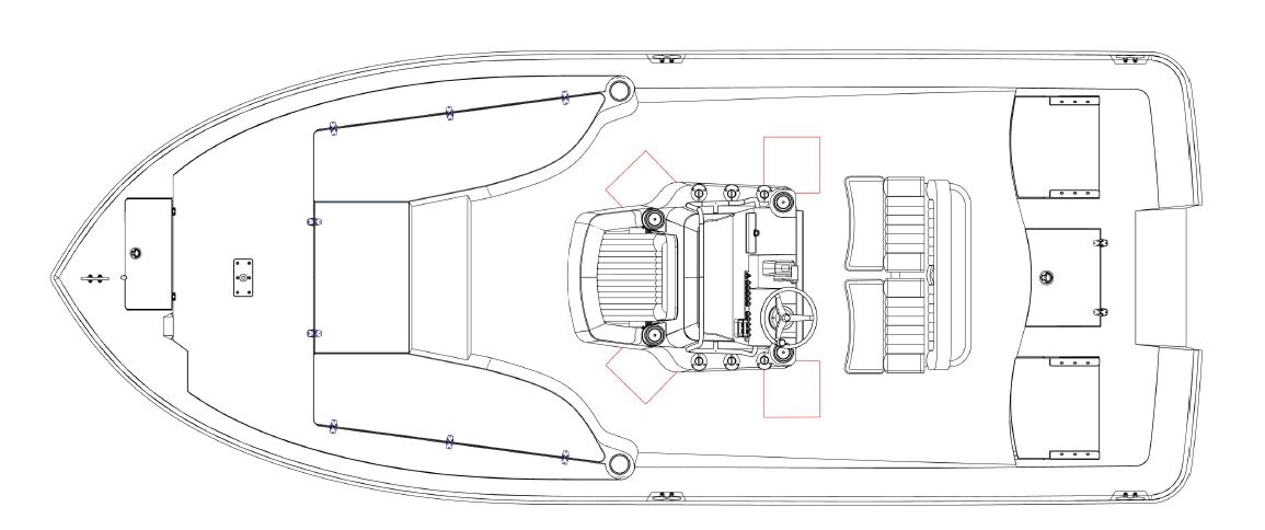
The Aluminum plates need for installation are 12”x12” x1/4”. The placement of the plats can vary by up to 1” during the construction process.
During factory installation, T-Top foot pads are glued and sealed to the deck with 5200 or similar compounds. To further secure the part to the deck, we recommend a screw Length of 2” into the Aluminum, 1-1/2” if into the general laminate. Finally, the deck laminate schedule at the Aluminum plates is typically 1-1/2”.
Finally, a toggle bolt is not recommended in the subject areas due to limited clearance under the deck.
Notice:
The attached document and information within this article are to be used by marine professionals who plan to install a T-Top or Hard Top on the Sea Born FX21 Bay. Please note that adding third party parts and accessories may void your manufacturers warranty. As such, we strongly recommend you consult your local Composite Research, Inc. dealer prior to installation.
Still Unsure?
If you’re still undecided if a T-Top is right for you, be sure to check out our post, Boat Buying 101: Should I Add a T-Top to My New Boat?
What is the fuel capacity of the Sundance SV-171?
Approximately 34 Gallons

In Loving Memory – Brad Miller
It is with great sadness that we announce the passing of one of our longest standing, well-known employees, Mr. Brad Miller. Brad, an 8+ year member of our sales and territory management, passed away during the evening hours of January 10th, 2018 at home in Waycross, Georgia.
My P58, P48, P52, P66, TM256, TM258, TM260, TM270W transom-mount transducer is not working well at speeds above 10 knots. What can I do?
Transom mount transducers—while they are the easiest to install, can be the hardest to get working properly at speed. Fine
adjustments are needed for good high speed performance.
Please check the following for troubleshooting your transom mount transducer:
- Transom mount transducers will not work at any speed if they are installed on a powerboat boat with inboard motors,
or any sailboat. - If you have a single engine outboard, or I/O, make sure that the unit is mounted on the starboard side of the boat, so it is
free from most prop wash. - If you have a twin, or triple engine outboard, or I/O make sure that the unit is mounted between the motors, as low as
possible, either on the flat section of the keel (if any), or slightly left or right of the vee. - If you are still seeing poor performance at speed, this usually indicates that the transducer needs to be mounted lower
so that more of the face of the transducer is in contact with the water at speed. - To make this adjustment, loosen the mounting screws, and slide the transducer 1/2″ lower and re-test. You may need to
re-drill holes. If you do so, be sure to seal the old holes with manufacturer approved, below the waterline caulking or
epoxy. - You also may want to add another plastic wedge (supplied with the installation kit) so that when looking at the side of
the transducer the back or stern of the transducer is noticably lower than the bow or front of the transducer. This angle
will not affect depth readings. Doing this adjustmant will help keep the transducer in hard contact with the water at
higher speeds.
The picture below illustrates lowering and angling your transom mount.
![]()
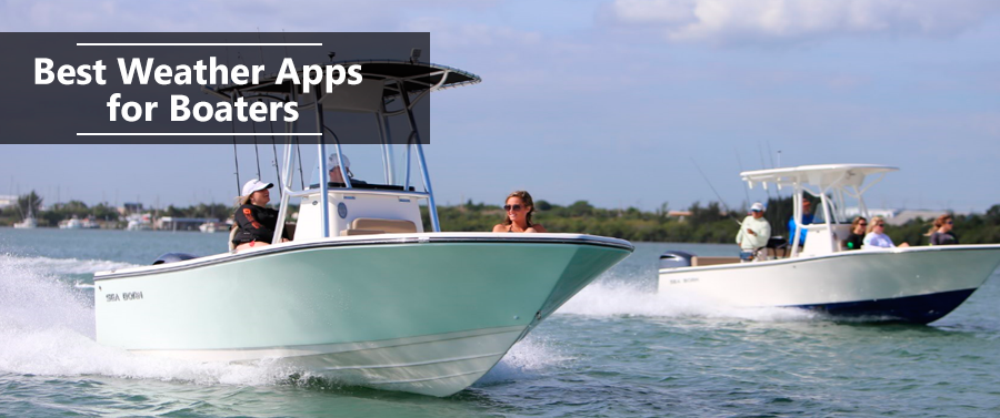
Best Weather Apps for Boating
One thing every all of us boaters comes to understand, we’re at the mercy of the weather and checking out the forecast is just part of the deal. To help you get a quick read on the forecast, we’ve worked up this quick list of useful weather apps for your tablet and smart phone.
What adhesive or caulking do you recommend for reattaching the rub rail?
We recommend using 3M 5200 marine sealant.
What is the dry hull weight of a 2005 Sundance SV17?
The approximate dry weight of the 2005 SV17 is 1,430.